
DIY Miniature Panorama Collection System
By Hillel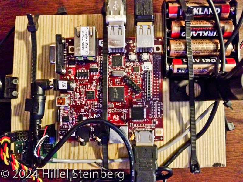
So Google didn’t hire you, but you still want to do cool things like engineer a miniature device to capture indoor 360 degree panoramas. Not to worry. The key to reaching this challenge lies in the art of breaking down goals into manageable pieces. You’ll need to build these pieces separately and then integrate. Finally, you can iterate your results stepwise toward perfection. While your device is short of perfection, however, you should probably call your progress “Beta”.
First, you’ll need a small computer platform to do the work on. This platform needs to be mobile so size is key. It will need to be powered by a portable battery source, and provide a wireless connection for access from your mobile device (e.g. phone). An Arduino, BeagleBoard, or Rasberry PI will do. For the purposes of this entry, I’ll just use the BeagleBoard TI ARM Cortex platform because, at the time of writing, it is currently the most capable and accessible of the three.
Before You begin in earnest, you will need to upgrade the OS provided with the board. The demo Angstrom build provided with the BeagleBoard is, to be honest, quite minimal and a bit outdated. A better bet is to grab a new 16gb MicroSD card and put the latest Ubuntu on it using instructions found here.
Once you have booted into Ubuntu, don’t forget to do an ‘apt-update’ and then an ‘apt-upgrade’ to ensure you have the latest software components. You will need to get “wireless” working early so you won’t need to drag a monitor/keyboard/mouse around with this device each time you deploy it. This will probably involve modifying the /etc/network/interfaces and /etc/wpa_supplicant files. Remember, ‘dmesg’, is your friend. Look around the web and you will find a lot of information on getting the wireless to work. The trick is to get a WIFI dongle that is small and yet fully supported by your Linux kernel. Make sure to use encryption, because you will be transmitting many images of the interiors of your location.
After you can connect remotely to your BeagleBoard, the next thing to try is to get a small webcam working with your Linux. You will need the lightest, smallest, highest resolution webcam you can find with reasonable driver support in Linux. You can use the video4linux API to access your webcam. You will know when you have the camera working in Linux when you see a /dev/video0 device file appear and executing the ‘dmesg’ command confirms that the webcam was detected.
There are many examples of video4linux code on the web that can capture a webcam image. Use a web example to create a function that simply grabs the highest quality picture you can get from the webcam and outputs it to a directory specified with a numbered filename. The file format can be JPEG, but don’t forget to use the highest (100%) quality settings because this is a lossy format. Test the new function by creating a driver to iterate several times. Try to make the capture system faster by carefully separating the ‘snap’ logic from the initialization logic. Then you can initialize once, and snap quickly. Make sure the files are written out correctly too, and none are missing when you complete. You will probably need to disable auto-gain, auto-white balance, and other parameters in the camera initialization code which will cause problems for stitching later. Video4linux has calls to get/set these parameters. There are plenty of examples on the web to show you how this is done.
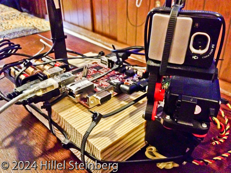
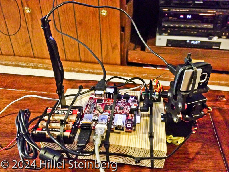
To move the camera, you will need a pair of reasonably powerful servos. A pair of Hitech/Futuba servos will do as well as this contraption to assist with the pan/tilt motion. Once you have put the two servos together, you will be wondering how the BeagleBoard will tell them to move. No problem. First, buy a servo controller such as the Maestro 12 Channel, and hook it up to the BeagleBoard via a USB cable. This cheap servo controller board when connected to the BeagleBoard should cause the Linux kernel to report (see ‘dmesg’) a new CDC ACM device, and the interface file /dev/ttyACM0 should appear. You can then hook the pan/tilt servos up to the Maestro on channel 0 & 1. You will need at least a separate 5v supply just to power the servos. You can do this by either using a single four AA/AAA battery pack or a two AA/AAA battery back with a voltage doubler. Your call. The four pack is heavier, but it’ll last longer.
There are many examples of code on the web that you can use to get your Pololu servo controller up and running. You should first use the included graphical Maestro configuration tool to set the servo to USB chaining mode. You can then experiment with the two servos to find and note their appropriate min/max values. You can use the code examples on their site to create a function that quickly points the servo towards a particular azimuth/elevation angle. Depending on your servos and your pan/tilt holder, you may not have a full 180/360 solution. Not to worry, you can iterate your design later. Again, separate the servo controller initialization code from the actual pointing functions. This will come handy during the integration phase.
You will next need to mount the camera on the pan/tilt holder. Initially, I recommend simply using ‘ties’. This will allow you to play with several configurations without having to screw or glue. Ideally you’ll want the camera to revolve only around its ‘nodal point’. This is not usually easy to do, but luckily, most modern panorama stitching software are smart enough to handle reasonable nodal point offsets. To minimize the camera’s nodal offset, it is best to place the lens as close to the holder pivot mechanism as possible. This may mean that the camera has to be oriented upside down or sideways. No problem – any good panorama stitching software can detect and correct image rotations.
By combining the two functions already designed above, you can now design a single application which iteratively moves the camera and writes high-quality images out to a sequential set of files in a designated output directory. The camera should pan and tilt to allow at least 20% overlap of each image with its neighbor’s. Upon capture termination, a metadata file can be written out to summarize how many pictures were captured, their capture times, orientations, and possibly the board’s GPS location. Once this application is up and functioning, you can add a Linux shell script to tar and compress the results on successful capture completion. You can even have the script upload the archive to another site via FTP, or to a SAMBA directory on a nearby laptop. It’s a pity that Dropbox support is minimal at this time for Linux. Though the BeagleBoard could perform the stitching directly, it is best to simply have the small ARM based board collect the pictures, and do the stitching on a platform that can handle the computation and memory necessary to do this activity properly. In addition, you can have the BeagleBoard collect panoramas and queue their output to a destination computer where the stitching can be done in parallel. In fact, the panorama capture, transfer, and stitching activities can all be done in parallel.
Along the way, you will find lots of ‘gotchas’. For example, as the pan/tilt mechanism moves, the USB wire attached to the camera will often get caught on one of the other system components (e.g., maestro 12). You can configure the USB cable in a variety of ways to avoid this from happening. When you are done stitching the panorama, you may find that the images aren’t aligned with enough overlap to achieve the desired stitching. When you write the pan/tilt stepping code, remember not bake hard coded values into the logic. You can do this by setting a system variable such as ‘overlap_percent’ to control the stepping behavior. This is a bit harder than just using a constant controller stepping value because you will need to translate ‘overlap_percent’ into a step size based on known camera specification parameters (e.g. FOV). The work will be worth it when you upgrade the system camera later to one which has different characteristics and parameters.
So, now you hook up your BeagleBoard, and you go to a room in your house, and start your collection application. The results are captured, transferred wirelessly to a computer nearby, and stitched without issue. Are you done? Not really, but we are starting to have fun – right? The problem is that wireless connections cannot be guaranteed wherever you go. That is, some indoor locations will not have WIFI, and others will not allow your device to connect to their Access Points. Even if you could connect wirelessly, you would still need to obtain the wireless parameters for each venue and communicate them somehow to the BeagleBoard for connection before the panorama collection process can begin. You could do this with an external keyboard/mouse/LCD panel, but that defeats the small and mobile aspects of this project. Another way is to use a mobile phone for hotspot tethering. This would be an easy way to guarantee a wireless connection in most places. Additionally, the hotspot parameters won’t change so the BeagleBoard can have a static wireless configuration.
But, what if there is no data service to your mobile device at a location? Again, no problem. As a backup plan, your background upload queue daemon on the BeagleBoard can hold up till a hotspot connection is restored. And, what if the BeagleBoard storage is nearly filled? You can have the background queue daemon also monitor the local storage device (SD card) periodically, and blink an LED light on the BeagleBoard via the board’s GPIO when space is limited. If the operator sees the blinking LED, the panorama archives can be transferred directly to an external portable hard drive. The same queuing and status daemon can additionally poll for an external hard drive. If the drive becomes active, the outstanding queued items can be transferred to the external drive and then removed from the local queue. Once the transfer is complete, the blinking light can cease.
BeagleBoard controlled lights can be used for more than just space notification. They can also be used to notify the operator that the device is ready, WIFI connection has been lost, or the battery is getting low. These are design elements that can be added iteratively over time. As the device is used in the field, feedback from operators will also drive new enhancements to the design. But, don’t try to do everything at once. Work on the parts separately and test them rigorously. It is also important not to minimize the importance of the component selection for your device. For example, a camera could be selected simply because of its low-power consumption and its reasonable MTBF. But, if it has poor resolution or low-light handling, the stitching may be impossible later. The best way to think of the field collection process is that it will only be done once. It may be feasible to return to a location for a subsequent capture, but it’s probably best to assume that the capture can only be done once due to expense, logistics, time constraints, or contractual agreements.
The same panorama collection setup on the BeagleBoard can be used for other projects requiring similar configurations. For example, a WII Nunchuk controller can be used to pan/tilt the camera “live” using it’s Bluetooth connection. The results are similar to security camera systems with operator control. Using a WIFI hotspot connection, it is naturally possible to extend such a system to one where the operator is situated remotely. Such a system can also prompt a remote user of movement via web services or an email. If you think outside-the-box, there is no telling how far you can take it.
Below is a short clip taken of the device I created during its capture operation very early in the development cycle. The setup is still crude here, but the camera functions well and yields a quite useable product. In later development stages, the mouse/keyboard/LCD are no longer needed, the device footprint is reduced significantly.
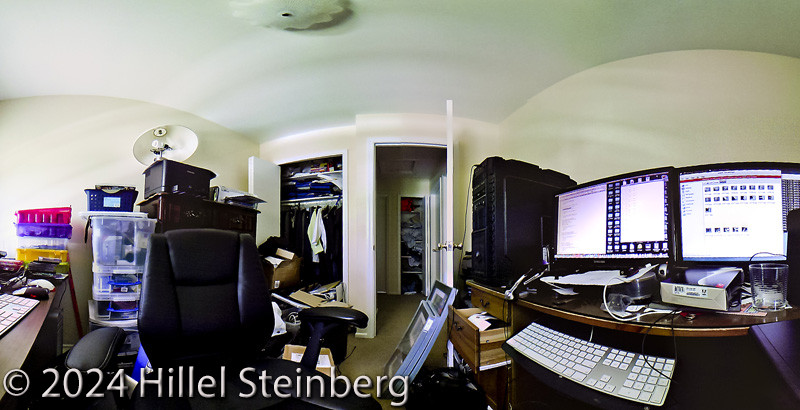
The first example stitched panorama output from the device is shown below. It is only a 180 degree collection set, but the results were easily stitched and the detail present is quite acceptable (the original is quite a bit bigger). In later development stages, the capture is a full 360 degree collection, and the resolution and detail are further increased. Stay tuned for the next BLOG entry which will cover other ways to utilize and build upon the current design.
[whohit]-RASPBERRYPI-[/whohit]